CombiBox is designed to connect the control unit to the Loader Combiloader and adapter DIALink 'on the table' and switching the supply voltage signals to GPT1, GPT2, and signal conditioning BOOT, CNF1.
Power supply.
To work CombiBox must submit the stabilized voltage supply of 12V. Mating connector included in the package. You must pay attention to the correct polarity when wiring power cable. Wrong power supply is UNACCEPTABLE and can lead to the exit CombiBox or is connected to control unit failure. To work CombiBox and safe programming of control units, it is recommended to use a regulated laboratory power supply with the voltage setting range up to 30 volts and a maximum current of at least 3 amps.
Connection.
On the rear of the CombiBox has 2 connectors:
1. DIALink connector intended for connection of the same name adapter. The connector has the following wiring diagram:
4 GND
5 GND
6 CAN-H
7 K-LINE
14 CAN-L
15 L-LINE
16 POWER
2. Combiloader – connector for the same name of the adapter.
On the front panel of the device is a connector of DB-25, designed to connect to the ECU using the supplied universal cable.
All lines of the cable are labeled for proper connection. The cable is equipped with additional pairs of contacts in the circuits 'VECU' and 'VKEY', which together allows you to serve up to eight voltages (four small and four large contact).
For convenience, the line GPT1 and GPT2 displayed in a separate bundle along with additional CAN-H and CAN-L.
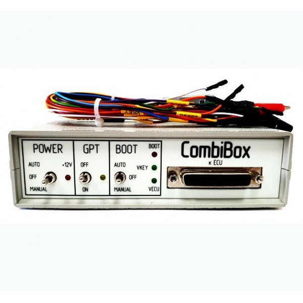
Controls.
Switch – GPT.
When enabled, this mode switching signal lines 7 and 15 of the DiaLink connector connector DB-25(GPT1 and GPT2) and at the same time a voltage is removed from the DiaLink connector. Used when reading the password in GPT mode. In the off state, the signal line 7 and 15 output connector DB-25(K-line and L-line), and the lines GPT1 and GPT2 are deenergized.
Switch - POWER, power management.
The device has three modes of supplying power to the ECU:
OFF, off, allows you to take all the supply and control signals from the DB-25 connector.
MANUAL, included, provides power to terminals VECU and VKEY, and control outputs depending on the selected tactics work switch BOOT.
AUTO, automatic control in this mode, the power management makes the loader CombiLoader.
Switch BOOT, simultaneous control signals BOOT and CNF1 (3.3 volts):
OFF, off, allows you to remove all of the control signals from the DB-25 connector.
MANUAL included, tightens the BOOT to the signal red, and CNF1 to +3.3 volts.
AUTO, automated operation, in this mode, the synchronous control signals produced by the loader CombiLoader.
The device has a built-in current-limiting resistors on signal lines:
RESET– 5.1 KOhm ( for st10 )
BOOT – 510 Ohm
CNF1 – 510 Ohm
CAN – 120 Ohm
Indicators:
GPT led indicator to indicate activation of the eponymous mode.
Led indicators VECU, VKEY specifies a voltage VECU, and VKEY.
12V led indicator indicates the presence of supply voltage.
Led BOOT indicator indicates the presence of CNF1 and suspenders to BOOT.