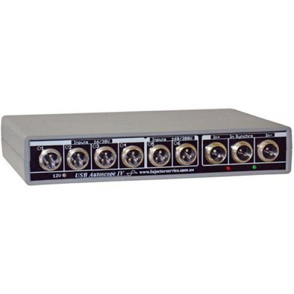
Digital oscilloscope USB Autoscope IV (oscilloscope Postolovsky) is an improved version of USB Autoscope III enables you to view, save, and analyze analog and digital signals with electrical circuits with the purpose of finding faults in electronic vehicle systems and diagnostics mechanics of gasoline engines. The device is connected to PC via USB port.
The main differences between USB Autoscope USB Autoscope IV III:
-
Built-in adapter plugs
-
The power sensor from the device
-
Convenient led illumination on the measuring adapters
-
Stand holder for sensor
Capabilities of the device:
-
Displaying waveform signals of the sensors and actuators with simultaneous recording and measuring of the test signal in real time
-
Analysis of oscillograms of primary and secondary voltages. Displaying waveforms in modes 'parade', 'raster', 'overlay'
-
Wide possibilities of analysis of parameters of signals - define the maximum/minimum/average voltage and difference voltage and time parameters of signals of pulse width, frequency, duty cycle and phase of the signal
-
Support for external embedded software modules (Plug-In) to run specific tests
-
Measurement of ignition timing (advance angle) and the pressure oscillogram in the cylinder (with appropriate sensor)
-
Graph display of discharge for assessment of the mechanics of the engine the method of research of character of change of vacuum in the intake manifold, measuring the level of pressure pulsations of the gases in the crankcase and in the exhaust pipe
-
Assessment of the relative compression in the engine cylinders on the basis of the waveform of the current starter (in the presence of a current clamp). It is known that the greater the compression in the cylinder, the greater the amplitude of pulsations of current of starter on the compression stroke in that cylinder
-
Automatic analysis of the recorded waveform on the basis of the VBScript or JScript files with the receipt of the report, as well as automatic marking and commenting characteristic plots of waveforms
-
Switch to analog inputs (possibility to connect your oscilloscope to any of the physical inputs 'on the fly')
-
The possibility of synchronizing according to any one of 8 channels oscilloscope (analyzer) with the choice of the synchronization mode for the front or rear to front
-
Saving the received data in JPEG format or a binary
-
The ability to edit the recorded signals
-
Ability to print current or stored waveform to a printer
-
The ability to create custom camera settings for commonly-used modes
-
Other
The device can operate in the following modes:
-
mode analog oscilloscope
-
the digital analyzer
-
diagnostics of the ignition system
-
schedule off
-
diagnostic mode timing system
-
the measurement mode of the ignition timing
-
mode timing measurement signal
-
measuring the relative fuel consumption
-
automatic waveform analysis
Operating modes:
-
Mode 1 -, 2 -, 4 -, and 8-channel analog oscilloscope
-
Mode digital (2) 4 or 8 channel digital analyzer
Mode analog oscilloscope:
|
Number of analog inputs
|
8
|
|
The number of channels of the oscilloscope
|
1, 2, 4, 8 (optional).
|
|
The resolution of the ADC
|
12-bit
|
|
The range of measured voltage
|
±6 / 30 V — 1-4 analog inputs;
±60 / 300 V — 5-6th analog input,
1-4th of the analog inputs when using an external input voltage divider 1:10;
±6 V — 7-8th analog input.
|
|
The maximum frequency of digitization per channel
|
in 1-channel mode 12.5 MHz;
in 2-channel mode 5.0 MHz;
in 4-channel mode — 2.5 MHz;
in 8 channel mode is 1.25 MHz.
|
|
Mode digitizing
|
a continuous flow
|
|
Input impedance
|
1 MΩ
|
|
Additional features
|
switch input channels
(the possibility of connecting channel
oscilloscope to any of the physical inputs
“the RAID”)
|
The digital analyzer:
|
The number of inputs of the digital analyzer
|
9
|
|
Input voltage range for digital analyzer
|
0...5.5 V
|
|
Modes
|
2 -, 4 -, 8-and canals�th analyzer
|
|
The maximum frequency of digitization per channel
|
in 2 channel mode — 100 MHz;
in 4-channel mode — 50 MHz;
in 8 channel mode — 25 MHz.
|
|
Input impedance
|
10 kΩ.
> 1 MΩ with voltage (0...5 V);
510 Ω if out of range
|
|
Maximum provide the device-side data flow
|
25MB/s
|
|
Current consumption
|
operating mode: less than 350mA
standby mode: not more than 60mA
|
The device provides continuous (without frame) mode of digitizing and transferring data to a PC. USB Autoscope IV is running of the USB Oscilloscope Program.
Options FOR USB Oscilloscope:
|
Main features
|
display mode + capture + measurements in real time simultaneously
|
|
Number of channels analog oscilloscope
|
selectable 1, 2, 4, (8)
|
|
Parameters sweep mode analog oscilloscope
|
1-channel mode — 2 μS / Div. — 1 S / Div.;
2-channel mode — 5 μS / Div. — 1 S / Div.;
4-channel mode — 10 μS / Div. — 1 S / Div.;
8-channel mode — 20 μS / Div. — 1 S / Div. with a step of 1-2-5.
|
|
Sweep parameters for digital analyzer
|
2-channel mode and 0.2 μS / Div. — 0.2 S / Div.;
4-channel mode is 0.5 μS / Div. — 0.5 S / Div.;
8-channel mode — 1 μS / Div. — 1 S / Div. with a step of 1-2-5.
|
|
Drill settings for voltage
(only analog mode of the oscilloscope)
|
for input voltage range ± 6 / 30 V
- 50 mV / Div. — 5 V / Div.;
for input voltage range ± 60 300 V
- 0.5 V / Div. — 50 V / Div.;
when using a capacitive sensor
- 500 V / Div. — 50 kV / Div.
|
|
- Sync mode analog oscilloscope
|
on any channel, front, level, threshold level, threshold, time
|
|
The number of channels of the digital analyzer
|
optionally, 2, 4, 8
|
|
Sweep parameters for digital analyzer
|
2-channel mode
0.2 MS/div. — 0.2 s/div.;
4-channel mode
0.5 MS/div. — 0.5 s/div.;
8-channel mode
1mks/del. — 1s/div.
with step 1-2-5
|
|
Sync mode digital analyzer
|
on any channel, front
|
|
The minimum recording time
(subject to the availability of free disk space)
|
mode analog oscilloscope:
1-channel mode (12.5 MHz)
- 170 seconds;
2-and 4-channel mode (10MHz)
- 240 sec;
the digital analyzer
- 85 sec.
With a decrease in the sampling rate the recording time increases in proportional to the number of times
|
|
The maximum file size
|
mode analog oscilloscope
- 3GB;
the digital analyzer
- 2GB
|
|
Measuring tools
|
max / min / average voltage, voltage difference, time, frequency, duty cycle and phase of the signal
|
|
Output formats
|
binary
graphic file format *.jpg,
obtaining hard copies of waveforms with printing
|
|
Additional features
|
Support for external embedded software modules PlugIn to run specific tests. The ability to create custom camera settings for commonly-used modes.
The mapping function value of the measured physical quantity.
To automate waveform analysis, has built-in implementation of the program waveform analysis according to an external algorithm written in script files analyzer. The possibility of compression / decompression “on the fly” while saving / reading the file. Simple editing functions binary file
|
Minimum computer requirements for Autoscope IV:
-
Microsoft Windows 98SE/ME/2000/XP/Vista/7/8
-
Pentium IV 2000 MHz
-
1024 MB of RAM
-
HDD 10 GB UDMA 100
-
USB 2.0 480 Mbps (HI-SPEED) port
Attention! The current consumption of any USB device must not exceed 500mA. The current consumption of the USB Autoscope IV in the operating mode is 180mA. But, despite this, when you enable USB Autoscope IV on some models of computers there is a decrease in the supply voltage +5V USB bus of the computer due to a failure in the power supply circuit of the computer's USB bus, USB Autoscope IV is not included and may not be regular complete work on such computers. To solve this problem on these computers by changing the settings in the BIOS, settings in Windows or device purchase USB Hub or a USB extension cable with extra power.
Equipment oscilloscope:
-
USB Autoscope - 1pc.
-
Power cable - 1pc.
-
USB 2.0 A/B cable - 1pc.
-
CD with software and documentation - 1pc.
-
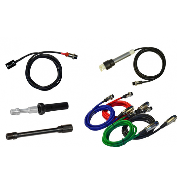
Dx (-0.85...+0.15 Bar) vacuum sensor + connecting cable - 1pc.
-
Sync sensor of the first cylinder to synchronize on the first cylinder - 1pc.
-
DIS Cx 6 set of capacitive sensors for the diagnosis of DIS ignition systems - 1pc.
-
Cx-M universal capacitive invoice d�tcic - 1pc.
-
Lx-M universal invoice inductive sensor - 1pcs.
-
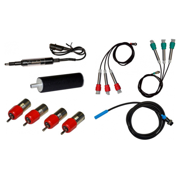
Px35 (-0,95...+35 bars) pressure sensor in the cylinder - 1pc.
-
Universal cable - 4pcs.
-
Measuring adapter - 4pcs.
-
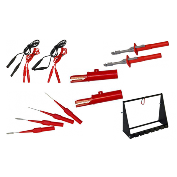
Stand holder tool - 1pc.
-
PxLonger extension cable for pressure sensor in the cylinder - 1pc.
-
Spark Gap high voltage spark gap - 1pc.
-
The probe-needle - 4pcs.
-
Probe-clip progulivali - 2pcs.
-
Probe-clip 'crocodile' - 2pcs.
-
Wire-extension bar - 4pcs.