Switching device for PCMflash PowerBox is designed to connect the control unit to the loader software 'on the table' and automatic (if supported by the bootloader and the J2534 adapter) or manual switching of supply voltages and the generation of signals RESET, BOOT, CNF1, GPT1, GPT2, WATCHDOG.
Working in automatic mode with the boot loaders that are used to control:
BOOT - OEM12, 12 contact OBD-II.
Managing supply - L-LINE, 15 contact OBD-II.
Important:
In the base cable not supplied. Cable tab, 'Companion'.
For 71 module PCMflash the BOOT switch must be in AUTO position. (The BOOT indicator should glow when power is applied to ECU), switch the ATG at position 5 volts.
In MANUAL mode - power need to apply it with a switch on the PowerBox , not from an external source.
In GPT mode allows you to operate with 3.3 v, 5V and 12v signals.
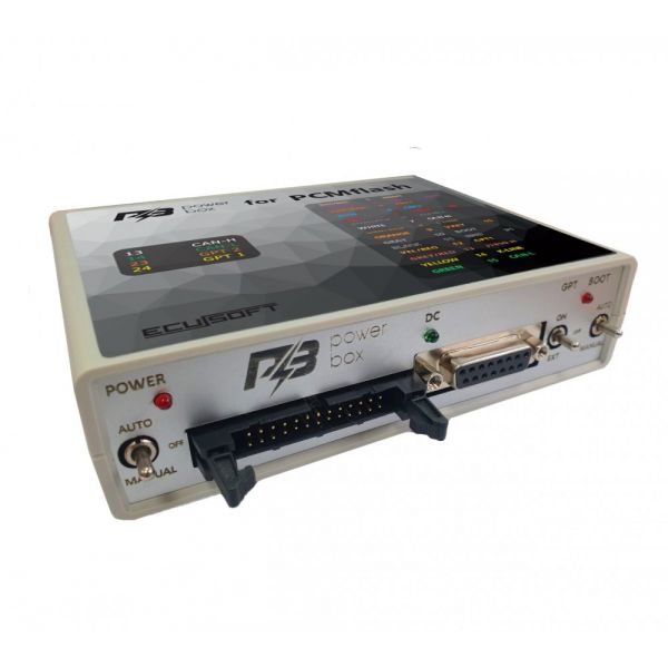
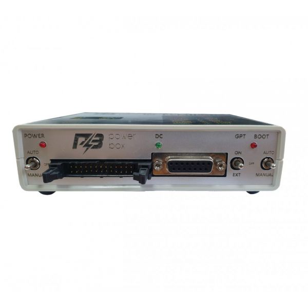
Controls:
The device is equipped with three switches for providing operation in different modes.
Switch - POWER, power management.
The device has three modes of supplying power to the ECU:
- OFF, off, allows you to take all the supply and control signals from the connectors IDC-26 and DB-15.
- MANUAL included, supply power to terminals VECU and VKEY, and control outputs depending on the selected tactics work.
-AUTO, auto control, in this mode the power management produces the boot loader signal in the L-Line (15 contact OBD-II).
Switch BOOT, simultaneous control signal BOOT, RESET, and CNF1 (3.3 volts):
- OFF, off, allows you to remove all of the control signals connector DB-15.
- MANUAL included, tightens RESET and BOOT to the signal red, and CNF1 to +3.3 volts.
-AUTO, auto-steer in this mode, the synchronous control signal BOOT, RESET, and CNF1 produces a loader (12 contact OBD-II OEM12).
For work built-in generator with 71 PCMflash module, the switch BOOT must be set to MANUAL or AUTO.
The device has a built-in current-limiting resistors on signal lines:
-RESET– 5.1 KOhm (in the earlier version till s/n:2050 installed 510 Ohm )
-BOOT – 510 Ohm
-CNF1 - 220 Ohm
The CAN bus has a terminal resistor of 120 Ohms.
To work with processors from Renesas and Tricore from a GPT device is equipped with a switch that changes the signal levels of 3.3 volts and 5 volts.
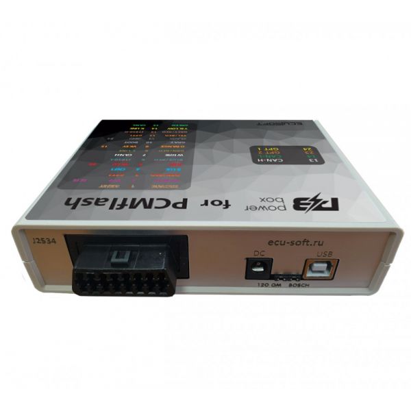
Connectors:
The device is equipped with multi-purpose connectors, allowing the user to make the connection.
USB connector for computer connection. Connector is required when using the built-in Converter USB to UART for software updates of the device PowerBox, but also when programming the processor brand Renesas.
DC connector designed to power the integrated circuit device and connected to the ECU. Recommended to use only quality power supplies with output voltage of 12 volts. When reading a password, when that is impossible by car, you need to consider that high-voltage converters in the ECU when you start to consume a sufficiently large current that may lead to protection or even cause damage to the power supply.
J2534 connector for connection of the eponymous interface with OBD-II connector.
The connector has the following wiring diagram:
4 GND
5 GND
6 CAN-H
7 K-LINE
12 SELECT BOOT
13 VPP
14 CAN-L
15 L-LINE
16 POWER
DB-15 connector for the ECU connection. It is recommended to use cable with a DB15 - PIN. The connector has the following wiring diagram:
1 RESET BROWN
2 VPP PURPLE
3 GPT2
4 CNF1 BLUE
5 VECU RED
7 CAN-H WHITE
9 VKEY ORANGE
10 BOOT GRAY
11 GND BLACK
12 GPT1
14 K-LINE YELLOW
15 CAN-L GREEN
IDC-26 connector for the ECU connection.
The connector has the following wiring diagram:
1 GND SIGNAL
2 VECU
3 VPP (Pin 13 of the OBD-II OEM13)
5 5V/3.3 V
6 GND
7 RXD
8 TXD
10 WATCHDOG
11 5V/3.3 V
12 K-LINE
13 CAN-H
14 CAN-L
15 GND
21 GND
23 GPT2
24 GPT1
Indicators:
The led indicator located next to switch 5V/3.3 V indicates the presence of voltage 5V or 3.3 V.
Led VECU, VKEY specifies a voltage VECU, and VKEY.
12V led indicator indicates the presence of supply voltage.
Led BOOT indicator indicates that voltage of 3.3 volts at the output of CNF1, braces to the downside to BOOT and RESET, and also points to the GPT regime (glow - 71 module\ off - 53 module).


![Bosch MG1/MD1 BENCH [SM2 only]](https://ecupro.eu/image/cache/data/products/bitboxlogo-70x70.png)
