Your shopping cart is empty!
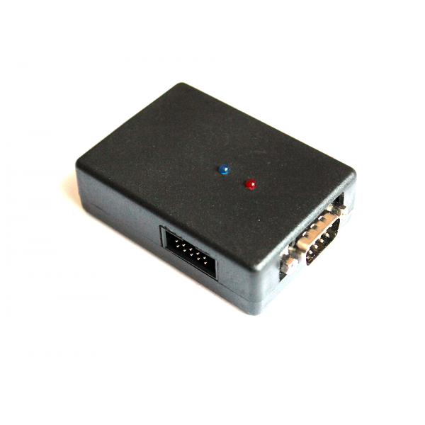
Universal programmer to work with ECU DENSO processor-based NEC to be installed in TOYOTA and LEXUS petrol and diesel engines through the JTAG interface and OBD2 diagnostic connector. The best solution for chip-tuning of cars Toyota and Lexus.
Toyota Flasher provides almost complete coverage of the entire range of ranging, approximately, from the 2004 release.
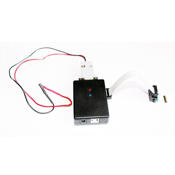
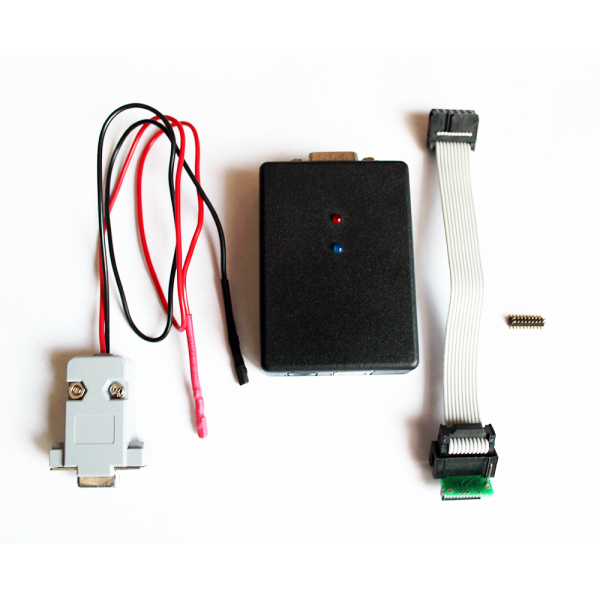
Includes:
Not included:
Software and driver http://www.autokey.com.ua/TOYOTA/HTML/TOYOTA_SOFT.html
Manual - http://pcmflash.ru/forum/viewtopic.php?f=1&t=74
Helpy - http://pcmflash.ru/toyota/
Activation instructions Toyota Flasher:
Preparation for use of the device:
0) only Use quality USB cable when working with the devices. 'Chinese' cable lose up to 0.5 V, which leads to the impossibility to operate the blocks.
1) Before you start, you need to install drivers for the virtual COM port the STM. Please note that at initial startup will be unpacked, the setup program, which must be run to install the driver. If you use other devices Autokey, then probably the required driver already installed.
2) After installing the drivers necessary to run the program, a link to which You will receive and, if necessary, to activate the device. For this, log into the Help menu, choose About, copy the Hardware Id and send the data to obtain the activation code to the seller.
3) Validating the device when trying to read and successfully determining the ID of the processor will display the message Interface is Locked.
Work with control units:
0) is Determined by the power of external data, this will check the presence of contacts 6 and 14 in the OBD connector (CAN bus) or make sure the diagnosis is on the CAN. Supported cars from about 2003-2004 to the present, these processors were introduced at the beginning of support CAN and usually when you change bodies. NOTE: a small sealed units in Camry 50 (all metal) and similar are not supported, because the PCB lacks place for the corresponding connector!
1) Remove engine control unit from the vehicle;
2) Reveal his body. If the block is sealed, it is necessary to separate the case halves, which are connected by a fragile layer of white sealant.
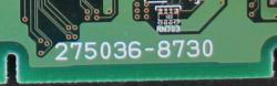
3) After gaining access to the PCB you should find her number listed in white and is found among those that prepared the help files (http://pcmflash.ru/toyota/).
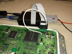
4) If one is found, then carry out the connection according to the figure the power wires connected to the main unit connectors (black wire (ground) to gray connector on the picture, the red wire (+12V) to red)

Raspivat on Board 20 pin connector (marked with orange), and prepare additional wire (on the circuit Board pad marked in red);
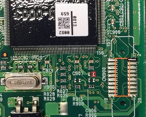
NOTE: if the Board uses a site for 26-pin connector, the connector should be installed with an offset in one contact.
5) Install transition adapter soldered on the connector, so that the point on the adapter is directed to the processor and connect the additional wire to the contact on the PCB;
6) connect power adapter 12V to the programmer and then implemented in the program reading (Read), erase (Erase) and a write (write) as required.
NOTE: before writing the internal flash it needs to be advanced�but erased.
What to do if the help file for this block no:
0) visually compare the cost with those that are in help, there might be very similar
If found - check that the 'power' of the Board is on the same contacts of the primary connector, similar to the method described below:
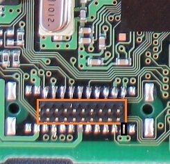
1) find a place under 20 or 26 contact connector, one probe of a multimeter set to the contact mass (the black rectangle in the pictures above), his position is always fixed, the second probe in continuity mode, find the relevant pin on the main connector.
NOTE: in the wiring of the car can be several contacts masses, some of them power, other logic, etc., so don't focus on the wiring diagram and wire colors, it is necessary to find the exact mass, which 'call' on socket programming.
2) after finding the contact mass, it is necessary to find contacts DC power supply unit, it needs to either read wiring diagram or you can find a similar connector to help, so to match a contact mass and a visual estimate of cost. Usually the positive contact is in its extreme right-hand socket, top row, 1 or 2 contact to the right (if the power connector is up to You). As this contact is usually double with each other and the conductors from it are connected to the positive side of capacitors and inductors.
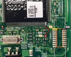
3) it is Necessary to determine the point on the Board to connect the additional contact. In all blocks with socket programming on the Board is a 10 kω resistor, one contact connected to ground (mass) and the second contact, the combined contact area, where provided (but not installed the same resistor), while its second contact connected to the inner stabilizer +5V. 20, and 26 contact connectors point +5V situated opposite the earth pin (marked in black). This 'middle' point of the resistors and connected to the additional contact.
The processors 76F0038(A), 76F0039(A), 76F0040(A) this mid-point always connects to a second right output (pin 155 CPU) located on the housing of the quartz resonator:
The processors 76F0070 and 76F0085 need to visually find and verify the connection pads of the resistors.
In case of difficulty, please contact support (canalyzer1@gmail.com) in advance of making pictures of circuit boards and connectors in high definition and defining the position of the contact mass.