Switching of CAN data bus signals of trucks with various connection standards to the OBD2 diagnostic pad to the standard outputs of ISO 15765 diagnostic devices (CAN High – output No. 6,CAN Low – output No. 14);
the ability to connect diagnostic adapters for a 12 volt onboard network (OpenPort 2.0, etc.) to a 24 volt onboard network of trucks;
protection of diagnostic devices from overvoltage in the vehicle's onboard network;
the possibility of connecting the terminal resistor of the CAN bus (R = 120 ohms) in its absence in the car.
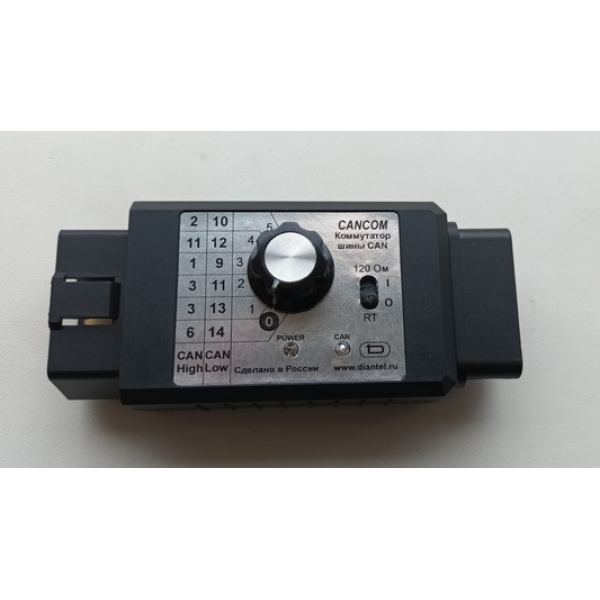
Controls and indications
The switch knob is used to switch between CAN lines. Possible connection options to the diagnostic OBD2 pad of the carcan-H/CAN-L: 6/14, 3/13, 3 /11, 1/9, 11/12, 2/10- The POWER indicator indicates that the switch is connected to the vehicle's onboard network.
The CAN indicator indicates data exchange via the CAN bus.
The RT switch connects the terminal resistor of the CAN bus (R=120 ohms) when it is not in the car.
Connection
The switch is connected between the CAN adapter's OBD connector and the vehicle's OBD connector.In all switch positions, the K-line (7), L-line (15) and 8th pin of the connector are transmitted from the input to the output, providing direct passage of the K-line and L-line lines.In the switch, the power supply line +AB (16) from the diagnostic OBD2 pads of the car is supplied to the adapter via a step-down voltage converter, which allows the use of 12 volt diagnostic adapters. In the switch position "0", the CAN bus remains on the standard terminals ((CAN High – output. No. 6, CAN Low – output№14);